
Page 229 - Optofluidics Fundamentals, Devices, and Applications
P. 229
204 Cha pte r Ni ne
exhibits a birefringent behavior that the incoming light may expe-
rience a different index of refraction depending on its state of
polarization. By varying the strength of the electric field in the
direction normal to the propagation of light, the liquid crystal
molecules can be oriented to create an index gradient radially, thus
(de)focusing the light passing the device [2]. Several groups have
utilized liquid crystals to create fluidic lenses. One example of the
liquid crystal fluidic lens is shown in Fig. 9-1.
One approach to control liquid crystals is by designing the elec-
trodes such that an axially symmetrical inhomogeneous electric field
is created in the liquid crystal layer [3]. This has been done by section-
ing the electrodes and applying different voltages [4–6] or by placing
curved glasses into the fluidic lens to change the spacing between the
electrodes [7–9]. Another approach to create liquid crystal fluidic lens
is by mixing liquid crystals with polymers. When the polymer polym-
erizes, it will lock the liquid crystal in its original orientation, keeping
it from moving when electric field is applied. This causes the lens to
have a varying index of refraction throughout the entire lens and cre-
ate the lensing effect [10–12].
There are several applications for the liquid crystal fluidic lens.
For instance, it has been applied to micro-lenses [13,14], confocal
microscopy [15], and disc storage systems [16,17].
Wavefront
Wavefront
φ3.0
μm ITO electrode Light beam
50 Substrate 3
No voltage
13 mm Substrate 2 V V Wave-
1 2
μm Substrate 1 Wavefront front
75
ITO electrode LC layer Al electrode
Wave-
Wavefront
front
Light beam Light beam
V > V 2 V < V 2
1
1
(a) (b)
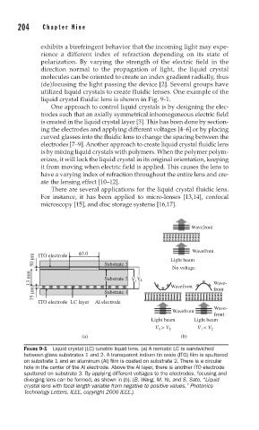
FIGURE 9-1 Liquid crystal (LC) tunable liquid lens. (a) A nematic LC is sandwiched
between glass substrates 1 and 2. A transparent indium tin oxide (ITO) fi lm is sputtered
on substrate 1 and an aluminum (Al) fi lm is coated on substrate 2. There is a circular
hole in the center of the Al electrode. Above the Al layer, there is another ITO electrode
sputtered on substrate 3. By applying different voltages to the electrodes, focusing and
diverging lens can be formed, as shown in (b). (B. Wang, M. Ye, and S. Sato, “Liquid
crystal lens with focal length variable from negative to positive values,” Photonics
Technology Letters, IEEE, copyright 2006 IEEE.)