
Page 80 - Optofluidics Fundamentals, Devices, and Applications
P. 80
Optofluidic Optical Components 61
In this section we describe in detail some of the major configurations
used for the realization of optofluidic waveguides.
4-2-1 Solid-Core/Liquid Clad Waveguide
The most straightforward and simple optofluidic waveguide config-
uration is a structure made of solid core surrounded by a liquid clad
(SCLC). A schematic sketch of such structure is shown in Fig. 4-1.
A solid core (typically made of glass, polymer, or semiconductor)
is positioned on top of a lower solid clad and covered by a liquid
forming the upper and side clad. Typical liquids being used for clad-
ding material are distilled [DI] water (n~1.33 at visible wavelength),
water-based solutions (n~1.33–1.45) and organic-based liquids
(n~1.45–1.55). Liquids with higher refractive indices, up to ~2.3, are
also available, although some of them are toxic. More details about
commercially available liquid solutions and their properties can be
found in Ref. 4. The solid lower clad is frequently made of silicon
dioxide (SiO , n~1.45). In some specific cases the SiO clad can be
2 2
etched (e.g., by buffered HF), forming a bridged waveguide. Such a
waveguide can be surrounded by liquid from all directions.
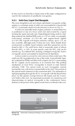
A silicon wafer is covered by a few microns–thick oxide layer. The
solid core (SC) is positioned on top of the oxide. A microfluidic chan-
nel is defined in PDMS and filled with a liquid clad (LC), surrounding
the SC. Liquids can be stationary or in constant flow. The guiding
mechanism of most SCLC waveguides is based on total internal
reflection (TIR). The optical mode in such waveguides extends
beyond the core, and decays exponentially in the clad. This portion of
the optical mode is known as the evanescent field. The interaction of
light propagating through the SCLC waveguide with the liquid takes
place via the spatial overlap between the liquid and the evanes-
cent field in the clad. An important parameter for classifying and
characterizing an optical waveguide is the confinement factor,
defined as the portion of the optical mode that is confined to the core.
PDMS
SC LC
SiO 2
Silicon wafer
FIGURE 4-1 Schematic drawing showing a cross section of a typical SCLC
waveguide.