
Page 81 - Optofluidics Fundamentals, Devices, and Applications
P. 81
62 Cha pte r F o u r
Most standard waveguides are designed to maximize the confine-
ment factor. However, if such designs are used for realizing SCLC
waveguides, only small fraction of light interacts with the liquid
cladding. The limited interaction of liquid with the optical mode is
considered as one of the fundamental drawbacks of the SCLC configu-
ration, limiting its usefulness for applications requiring large tuning
range or high sensitivity sensors. This obstacle, however, can be over-
come, at least partially, by proper design and optimization of the
waveguide geometry and refractive index distribution. For example,
one can increase the refractive index of the liquid, such that the opti-
cal mode expands much beyond the core. Alternatively, one can
reduce the size of the core, resulting in a lower mode confinement
and in turn larger interaction of the optical mode with the liquid clad.
This, however, results in an increase in bending loss and sometimes
(if the waveguide size or the refractive index difference goes down
beyond a critical point) even an increase in mode size, posing a strin-
gent limitation on the miniaturization of on-chip optofluidic integrated
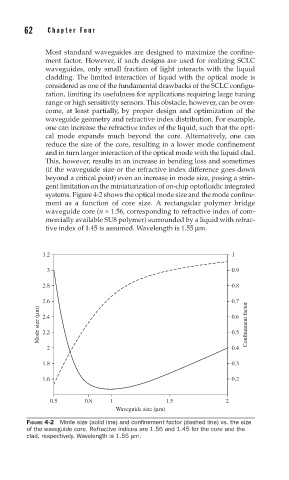
systems. Figure 4-2 shows the optical mode size and the mode confine-
ment as a function of core size. A rectangular polymer bridge
waveguide core (n = 1.56, corresponding to refractive index of com-
mercially available SU8 polymer) surrounded by a liquid with refrac-
tive index of 1.45 is assumed. Wavelength is 1.55 μm.
3.2 1
3 0.9
2.8 0.8
2.6 0.7
Mode size (μm) 2.4 0.6 Confinement factor
2.2
0.5
2 0.4
1.8 0.3
1.6 0.2
0.5 0.8 1 1.5 2
Waveguide size (μm)
FIGURE 4-2 Mode size (solid line) and confi nement factor (dashed line) vs. the size
of the waveguide core. Refractive indices are 1.56 and 1.45 for the core and the
clad, respectively. Wavelength is 1.55 μm.