Page 120 -
P. 120

Walter’s Turtle   107

                                                   1
                                                  3 / 2 in

                                                                       1
                                1
                               4 / in                                 4 / in
                                 2
                                                                        2
                                                    1
                                                  14 / in
                                                     2
                        1 in                                                  1 in

                                                                          1
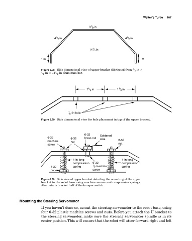
                        Figure 8.28  Side dimensional view of upper bracket fabricated from  � ­in �
                        1       1                                          8
                        � ­in �  14 � ­in aluminum bar.
                                 2
                         2
                                                  1
                                                                   1
                                                 1 /  in          1 /  in
                                                   8
                                                                    8


                                      1 /  -in hole
                                       8
                        Figure 8.29  Side dimensional view for hole placement in top of the upper bracket.


                                                6-32    Soldered
                           6-32         6-32    brass nut  wire
                           machine      nut                       6-32
                           screw                                  nut


                                         1-in-long                  1-in-long
                                         compression  6-32          compression
                             6-32        spring     1 / machine     spring
                                                     2
                             nut                    screw

                        Figure 8.30  Side view of upper bracket detailing the mounting of the upper
                        bracket to the robot base using machine screws and compression springs.
                        Also details bracket half of the bumper switch.


            Mounting the Steering Servomotor
                        If you haven’t done so, mount the steering servomotor to the robot base, using
                        four 6­32 plastic machine screws and nuts. Before you attach the U bracket to
                        the steering servomotor, make sure the steering servomotor spindle is in its
                        center position. This will ensure that the robot will steer forward right and left
   115   116   117   118   119   120   121   122   123   124   125