Page 119 -
P. 119

106   Chapter Eight

                                                    1
                                                   3 / 2 in

                                                                        1
                                 1
                                4 / 2 in                               4 / 2 in


                                                   32 in

                         3
                                                                              3
                        4 / 4 in                                              4 / 4 in


                                                    1
                                                   9 / 2 in
                                                                            1
                                                                      1
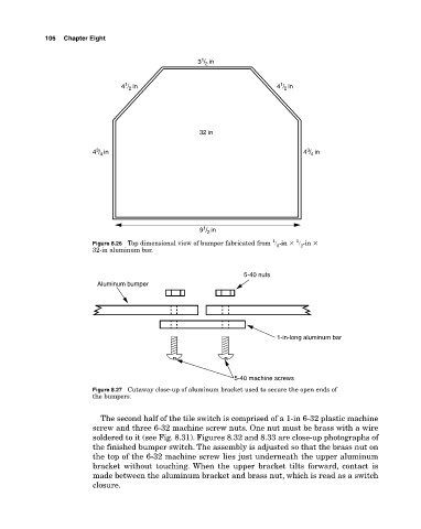
                        Figure 8.26  Top dimensional view of bumper fabricated from  � ­in �  � ­in �
                                                                       8
                                                                             2
                        32­in aluminum bar.
                                                              5-40 nuts
                          Aluminum bumper


                                                                       1-in-long aluminum bar


                                                            5-40 machine screws
                        Figure 8.27  Cutaway close­up of aluminum bracket used to secure the open ends of
                        the bumpers.

                          The second half of the tile switch is comprised of a 1­in 6­32 plastic machine
                        screw and three 6­32 machine screw nuts. One nut must be brass with a wire
                        soldered to it (see Fig. 8.31). Figures 8.32 and 8.33 are close­up photographs of
                        the finished bumper switch. The assembly is adjusted so that the brass nut on
                        the top of the 6­32 machine screw lies just underneath the upper aluminum
                        bracket without touching. When the upper bracket tilts forward,  contact is
                        made between the aluminum bracket and brass nut, which is read as a switch
                        closure.
   114   115   116   117   118   119   120   121   122   123   124