Page 114 -
P. 114

Walter’s Turtle   101

                                                  1 / 8  - in holes


                                                     3
                                                    2 / 4 in


                                          125°                                 10 in
                          3
                         2 / 4 in
                                                                                         Wheel


                                                    5
                                                   3 / 8 in
                3
                 / 4 in
                                                              Axle
                                                              Height
                             1 / - in hole for axle                 1 / - in hole for axle
                              8
                                                                     8


                                      Wheel size                                       2 in


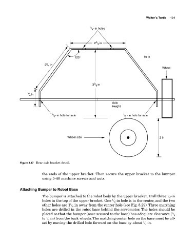
            Figure 8.17  Rear axle bracket detail.

                        the ends of the upper bracket. Then secure the upper bracket to the bumper
                        using 5­40 machine screws and nuts.


            Attaching Bumper to Robot Base
                                                                                            1
                        The bumper is attached to the robot body by the upper bracket. Drill three  � ­in
                                                                                             8
                                                              1
                        holes in the top of the upper bracket. One  � ­in hole is in the center, and the two
                                                               8
                                       1
                        other holes are 1 � in away from the center hole (see Fig. 8.29). Three matching
                                        8
                        holes are drilled in the robot base behind the servomotor. The holes should be
                        placed so that the bumper (once secured to the base) has adequate clearance ( �
                                                                                              1
                                                                                               8
                          1
                        to  � in) from the back wheels. The matching center hole on the base must be off­
                           4
                                                                               1
                        set by moving the drilled hole forward on the base by about  � in.
                                                                                4
   109   110   111   112   113   114   115   116   117   118   119