
Page 113 -
P. 113
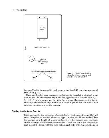
100 Chapter Eight
42-oz
servo
Front Sheet metal 3 in x 5.5 in
1 / 2 Ø wire
pass-through
hole
1 / 8 - in holes to match rear axle bracket
Figure 8.16 Robot base showing
cutout for 42oz servomotor and
holes for rear axle bracket.
bumper. The bar is secured to the bumper using two 540 machine screws and
nuts (see Fig. 8.27).
The upper bracket used to connect the bumper to the robot is identical to the
front end of the bumper (see Fig. 8.28). The upper bracket is made from � �
1
8
1 � � 14.5in aluminum bar. As with the bumper, the center of the bar is
2
marked, and each bend required is also marked in pencil. The material is bent
in a vise the same way as the bumper.
Finding the Center of Gravity
It is important to find the center of gravity line of the bumper, because this will
mark the optimum location where the upper bracket should be attached. Rest
the bumper on a length of aluminum bar. Move the bumper back and forth
until it balances evenly on the aluminum bar. Mark the centerline positions on
1
each side of the bumper. Drill a � in hole on each side. Drill matching holes on
8