
Page 112 -
P. 112
Walter’s Turtle 99
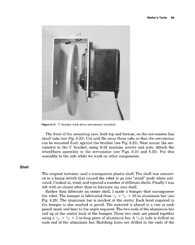
Figure 8.15 U bracket with drive servomotor attached.
The front of the mounting ears, both top and bottom, on the servomotor has
small tabs (see Fig. 8.22). Cut and file away these tabs so that the servomotor
can be mounted flush against the bracket (see Fig. 8.23). Next mount the ser
vomotor to the U bracket, using 632 machine screws and nuts. Attach the
wheel/horn assembly to the servomotor (see Figs. 8.24 and 8.25). Put this
assembly to the side while we work on other components.
Shell
The original tortoises used a transparent plastic shell. The shell was connect
ed to a bump switch that caused the robot to go into “avoid” mode when acti
vated. I looked at, tried, and rejected a number of different shells. Finally I was
left with no choice other than to fabricate my own shell.
Rather than fabricate an entire shell, I made a bumper that encompasses
1
1
the robot. The bumper is fabricated from � � � � 32in aluminum bar (see
8
2
Fig. 8.26). The aluminum bar is marked at the center. Each bend required in
the bumper is also marked in pencil. The material is placed in a vise at each
pencil mark and bent to the angle required. The two ends of the aluminum bar
end up at the center back of the bumper. These two ends are joined together
1
1
1
using a � � � � 1inlong piece of aluminum bar. A � in hole is drilled on
8
8
2
each end of the aluminum bar. Matching holes are drilled in the ends of the