
Page 75 -
P. 75
62 Chapter Six
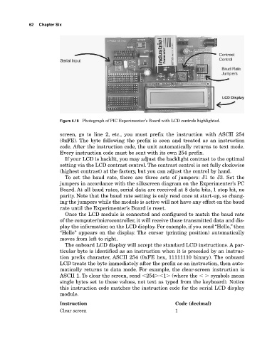
Figure 6.18 Photograph of PIC Experimenter’s Board with LCD controls highlighted.
screen, go to line 2, etc., you must prefix the instruction with ASCII 254
(0xFE). The byte following the prefix is seen and treated as an instruction
code. After the instruction code, the unit automatically returns to text mode.
Every instruction code must be sent with its own 254 prefix.
If your LCD is backlit, you may adjust the backlight contrast to the optimal
setting via the LCD contrast control. The contrast control is set fully clockwise
(highest contrast) at the factory, but you can adjust the control by hand.
To set the baud rate, there are three sets of jumpers: J1 to J3. Set the
jumpers in accordance with the silkscreen diagram on the Experimenter’s PC
Board. At all baud rates, serial data are received at 8 data bits, 1 stop bit, no
parity. Note that the baud rate setting is only read once at startup, so chang
ing the jumpers while the module is active will not have any effect on the baud
rate until the Experimenter’s Board is reset.
Once the LCD module is connected and configured to match the baud rate
of the computer/microcontroller, it will receive those transmitted data and dis
play the information on the LCD display. For example, if you send “Hello,” then
“Hello” appears on the display. The cursor (printing position) automatically
moves from left to right.
The onboard LCD display will accept the standard LCD instructions. A par
ticular byte is identified as an instruction when it is preceded by an instruc
tion prefix character, ASCII 254 (0xFE hex, 11111110 binary). The onboard
LCD treats the byte immediately after the prefix as an instruction, then auto
matically returns to data mode. For example, the clearscreen instruction is
ASCII 1. To clear the screen, send �254��1� (where the �� symbols mean
single bytes set to these values, not text as typed from the keyboard). Notice
this instruction code matches the instruction code for the serial LCD display
module.
Instruction Code (decimal)
Clear screen 1