
Page 76 -
P. 76
Testing the PIC Microcontroller 63
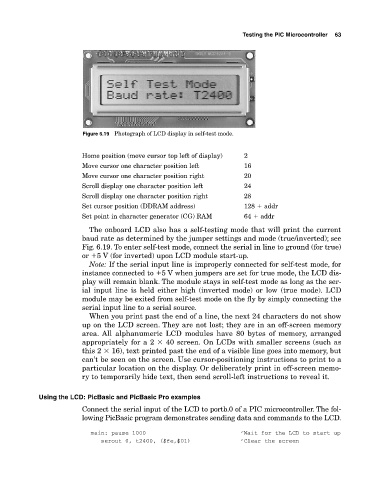
Figure 6.19 Photograph of LCD display in selftest mode.
Home position (move cursor top left of display) 2
Move cursor one character position left 16
Move cursor one character position right 20
Scroll display one character position left 24
Scroll display one character position right 28
Set cursor position (DDRAM address) 128 � addr
Set point in character generator (CG) RAM 64 � addr
The onboard LCD also has a selftesting mode that will print the current
baud rate as determined by the jumper settings and mode (true/inverted); see
Fig. 6.19. To enter selftest mode, connect the serial in line to ground (for true)
or �5 V (for inverted) upon LCD module startup.
Note: If the serial input line is improperly connected for selftest mode, for
instance connected to �5 V when jumpers are set for true mode, the LCD dis
play will remain blank. The module stays in selftest mode as long as the ser
ial input line is held either high (inverted mode) or low (true mode). LCD
module may be exited from selftest mode on the fly by simply connecting the
serial input line to a serial source.
When you print past the end of a line, the next 24 characters do not show
up on the LCD screen. They are not lost; they are in an offscreen memory
area. All alphanumeric LCD modules have 80 bytes of memory, arranged
appropriately for a 2 � 40 screen. On LCDs with smaller screens (such as
this 2 � 16), text printed past the end of a visible line goes into memory, but
can’t be seen on the screen. Use cursorpositioning instructions to print to a
particular location on the display. Or deliberately print in offscreen memo
ry to temporarily hide text, then send scrollleft instructions to reveal it.
Using the LCD: PicBasic and PicBasic Pro examples
Connect the serial input of the LCD to portb.0 of a PIC microcontroller. The fol
lowing PicBasic program demonstrates sending data and commands to the LCD.
main: pause 1000 ‘Wait for the LCD to start up
serout 0, t2400, ($fe,$01) ‘Clear the screen