
Page 13 - Packed bed columns for absorption, desorption, rectification and direct heat transfer
P. 13
« liquid flow .Screen mesh
< Gas flow
imm
deflection plate
Top mem
—Packing
A L and A Q
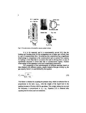
Fig. 3. Principle scheme of a crossflow cascade packed column.
It is to be expected, and it is experimentally proved [41], that the
loading and flooding point for this arrangement are at higher gas velocity than
in case of countercurrent flow. Nevertheless this construction has a significant
disadvantage in comparison to the countercurrent and co-current flow, namely
its loading is lower than that in co-current flow and ite driving force in case of
equilibrium processes is lower than that in countercurrent regime. Another
disadvantage of this apparatus is the more complicated construction.
For comparison of the hydrodynamics of different packings based on
data obtained with different systems, usually instead of the gas velocity Wg, the
gas capacity factor C, is used defined by the equation
Pa
(13)
PL-PG
This factor is obtained by equating the pressure drop, which in turbulent flow is
proportional to the term w$ p G, with the weight of the liquid held in the
packing because of friction with the gas phase. This weight, taking into account
the buoyancy, is proportional to Pi~Pa- Equation (13) is obtained after
equating the two terms and root extraction.