
Page 315 - Packed bed columns for absorption, desorption, rectification and direct heat transfer
P. 315
301
10
B 8 10 2
w n ,m/s
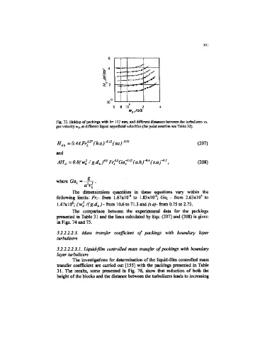
Fig. 73. Holdup of packings with &= 117 mm, and different distances between the turbulizers vs.
gai velocity wj, at different liquid superficial velocities (for point notation see Table 32).
(207)
and
2
2
4
AH, = 0.8(w /g.d rF4 Ga^"(a.hr (s. ) -° J (208)
0
h
a
g
where Ga L =
The dimensionless quantities in these equations vary within the
2
4
4
following limits: Fr L- from 1.67X10" to U3xlO" ; Ga L - from 2.63x10 to
6 2
1.47xlO ; (w 0 /(g.d h ) - from 10.6 to 71.3 and (s.a)- from 0.75 to 2.73.
The comparison between the experimental data for the packings
presented in Table 31 and the lines calculated by Eqs. (207) and (208) is given
in Figs. 74 and 75.
3.2.2.2.2.3. Mass transfer coefficient of packings with boundary layer
turbulizers
3.2.2.2.2.3.1. Liquid-film controlled mass transfer of packings with botmdary
layer turbulizers
The investigations for determination of the liquid-film controlled mass
transfer coefficient are carried out [155] with the packings presented in Table
31. The results, some presented in Fig. 76, show that reduction of both the
height of the blocks and the distance between the turbulizers leads to increasing