
Page 258 - Automobile Mechanical and Electrical Systems Automotive Technology Vehicle Maintenance and Repair (Vehicle Maintenance Repr Nv2) by Tom Denton
P. 258
2
242 Automobile mechanical and electrical systems
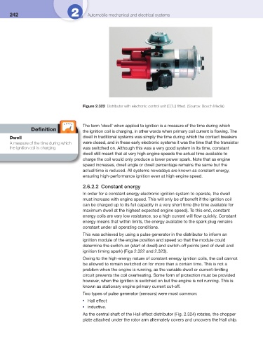
Figure 2.322 Distributor with electronic control unit (ECU) fi tted. (Source: Bosch Media)
The term ‘dwell’ when applied to ignition is a measure of the time during which
Defi nition
the ignition coil is charging, in other words when primary coil current is fl owing. The
Dwell dwell in traditional systems was simply the time during which the contact breakers
A measure of the time during which were closed, and in these early electronic systems it was the time that the transistor
the ignition coil is charging. was switched on. Although this was a very good system in its time, constant
dwell still meant that at very high engine speeds the actual time available to
charge the coil would only produce a lower power spark. Note that as engine
speed increases, dwell angle or dwell percentage remains the same but the
actual time is reduced. All systems nowadays are known as constant energy,
ensuring high-performance ignition even at high engine speed.
2.6.2.2 Constant energy
In order for a constant energy electronic ignition system to operate, the dwell
must increase with engine speed. This will only be of benefi t if the ignition coil
can be charged up to its full capacity in a very short time (the time available for
maximum dwell at the highest expected engine speed). To this end, constant
energy coils are very low resistance, so a high current will fl ow quickly. Constant
energy means that within limits, the energy available to the spark plug remains
constant under all operating conditions.
This was achieved by using a pulse generator in the distributor to inform an
ignition module of the engine position and speed so that the module could
determine the switch-on (start of dwell) and switch-off points (end of dwell and
ignition timing spark) ( Figs 2.322 and 2.323 ).
Owing to the high-energy nature of constant energy ignition coils, the coil cannot
be allowed to remain switched on for more than a certain time. This is not a
problem when the engine is running, as the variable dwell or current-limiting
circuit prevents the coil overheating. Some form of protection must be provided
however, when the ignition is switched on but the engine is not running. This is
known as stationary engine primary current cut-off.
Two types of pulse generator (sensors) were most common:
Hall effect
●
inductive.
●
As the central shaft of the Hall effect distributor ( Fig. 2.324 ) rotates, the chopper
plate attached under the rotor arm alternately covers and uncovers the Hall chip.