
Page 259 - Automobile Mechanical and Electrical Systems Automotive Technology Vehicle Maintenance and Repair (Vehicle Maintenance Repr Nv2) by Tom Denton
P. 259
2
Engine systems 243
Figure 2.323 Electronic ignition module. (Source: Bosch Media)
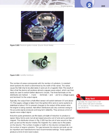
Figure 2.324 Hall effect distributor
The number of vanes corresponds with the number of cylinders. In constant
dwell systems the dwell is determined by the width of the vanes. The vanes
cause the Hall chip to be alternately in and out of a magnetic fi eld. The result of
this is that the device will produce almost a square-wave output, which can then
easily be used to switch further electronic circuits. The three terminals on the
distributor are marked , 0 and : terminals and are for a voltage supply
and terminal 0 is the output signal.
Key fact
Typically, the output from a Hall effect sensor will switch between 0 V and about
Typically, the output from a Hall
7 V. The supply voltage is taken from the ignition ECU and on some systems is
effect sensor will switch between
stabilized at about 10 V to prevent changes to the output of the sensor when 0 V and about 7 V (but always check
the engine is being cranked. Hall effect distributors are very common owing to specifi cations).
the accurate signal produced and long-term reliability. They produce a kind of
square-wave output signal.
Inductive pulse generators use the basic principle of induction to produce a
signal. Many forms exist, but all are based around a coil of wire and a permanent
magnet. The distributor shown in Fig. 2.325 has the coil of wire wound on the
pick-up and as the reluctor rotates the magnetic fl ux varies due to the peaks
on the reluctor. The number of peaks or teeth on the reluctor corresponds to
the number of engine cylinders. The gap between the reluctor and pick-up can
be important and manufacturers have recommended settings. These systems
produce a kind of sine-wave output.