
Page 145 - Petroleum and Gas Field Processing
P. 145
Use Eq. (17) to check the liquid capacity (retention time) constraint:
2
D L ¼ 1:429ð3000 10 þ 8000 15Þ¼ 214;350 ðE2Þ
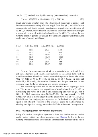
Select diameters smaller than the determined maximum diameter and
determine the corresponding effective length from Eqs. (E1) and (E2) for the
gas capacity and liquid capacity constraints, respectively. Investigation of
Eq. (E1), however, shows that for any selected diameter, the effective length
is too small compared to that calculated from Eq. (E2). Therefore, the gas
capacity does not govern the design. For the liquid capacity constraints, the
results are tabulated as follows:
D (in.) L (ft) [Eq. (E2)] L s ( ¼ 4L/3) (ft) L/(d/12)
66 49.21 65.61 11.93
72 41.35 55.13 9.19
78 35.23 46.98 7.23
84 30.38 40.50 5.786
90 26.46 35.28 4.71
96 23.26 31.01 3.88
102 20.65 27.47 3.23
Because the most common slenderness ratio is between 3 and 5, the
last three diameter and length combinations in the above table will be
suitable selections. Therefore, the recommended separator size can be either
90 in. by 36 ft, or 96 in. by 31 ft, or 102 in. by 28 ft based on cost and
availability. Normally, the smaller diameter and longer separator is less
expensive than the larger diameter and shorter separator.
The selected separator will be able to handle a much higher gas flow
rate. The actual separator gas capacity can be calculated from Eq. (8) by
substituting the values of d and L and calculating the value of Q g . For a
96-in. by 31-ft separator (L ¼ 3L s /4 ¼ 23.26), the gas capacity is 263
MMSCFD. This is much larger than the production rate of 8 MMSCFD.
This indicates that designing the separator on the basis of being half full of
liquid is not efficient. The size of the separator could be made smaller by
allowing the liquid to occupy more than half the volume of the separator.
4.5.2 Sizing Equation for Vertical Separators
Sizing of a vertical three-phase separator is done in a similar manner to that
used in sizing vertical two-phase separators (see Chapter 3); that is, the gas
capacity constraint is used to determine the minimum diameter of the vessel
Copyright 2003 by Marcel Dekker, Inc. All Rights Reserved.