
Page 97 - Petroleum and Gas Field Processing
P. 97
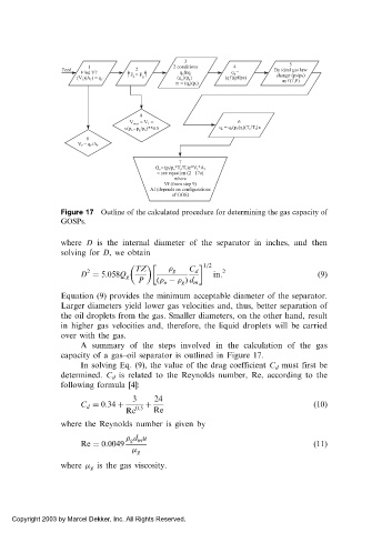
Figure 17 Outline of the calculated procedure for determining the gas capacity of
            GOSPs.

            where D is the internal diameter of the separator in inches, and then
            solving for D, we obtain
                                               1=2
                  2           TZ        g  C d     2
                 D ¼ 5:058Q g                    in:                      ð9Þ
                               P   ð  o     g Þ d m
            Equation (9) provides the minimum acceptable diameter of the separator.
            Larger diameters yield lower gas velocities and, thus, better separation of
            the oil droplets from the gas. Smaller diameters, on the other hand, result
            in higher gas velocities and, therefore, the liquid droplets will be carried
            over with the gas.
                 A summary of the steps involved in the calculation of the gas
            capacity of a gas–oil separator is outlined in Figure 17.
                 In solving Eq. (9), the value of the drag coefficient C d must first be
            determined. C d is related to the Reynolds number, Re, according to the
            following formula [4]:
                             3     24
                 C d ¼ 0:34 þ  0:5  þ                                    ð10Þ
                            Re    Re
            where the Reynolds number is given by
                              g d m u
                 Re ¼ 0:0049                                             ð11Þ
                               g
            where   g is the gas viscosity.


 Copyright 2003 by Marcel Dekker, Inc. All Rights Reserved.