
Page 215 - Petrophysics
P. 215
188 PETROPHYSICS: RESERVOIR ROCK PROPERTIES
zonation index is calculated from Equation 3.134, and the larger
value, which denotes the best division into two zones, is retained
for comparison with other indices.
(b) The permeability data of the best two-zone combination are divided
into all possible three, zone combinations. The index Iz is again
calculated for determining the best three-zone division.
(c) The permeability data of the best three-zone combinations are
divided into all possible four-zone combinations. Then the zonation
index criterion is applied.
The division into additional zones continues until the difference between
two successive indices, AIz, is negligible. Testerman found that the
difference is negligible if AIz -= 0.06 [55].
After all the wells in the reservoir have been zoned, the zones between
adjacent wells are correlated for determining which strata are likely to
be continuous, i.e., connected. Zones are considered to be connected if
the difference in mean permeability of two zones is adjoining wells is less
than or equal to that expected from variations of measurements within
zones.
EXAMPLE
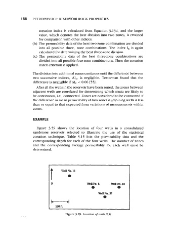
Figure 3.59 shows the location of four wells in a consolidated
sandstone reservoir selected to illustrate the use of the statistical
zonation technique. Table 3.15 lists the permeability data and the
corresponding depth for each of the four wells. The number of zones
and the corresponding average permeability for each well must be
determined.
t o
well No. 11
N
U
loo ft
Figure 3.59. Location of wells f55f*