
Page 432 - Petrophysics
P. 432
400 PETROPHYSICS: RESERVOIR ROCK PROPERTIES
I
. "Y
...... ....................
...... ....................
-#do--
-#do--
- 80-
L
c
bp
e 60-
d -
- S~=(3.6)'/~
S~=(3.6)'/~
$ 40- ---
Sw=(.20)1/"
v) .. --- Sw=(.20)1/"
a ......
I
W I,.
t 20-
B
0; I I I I I I
0 2 4 6 8 10 12
SATURATION EXPONENT (n)
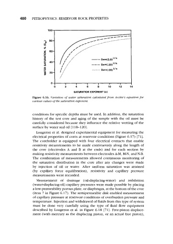
Figure 6.16. Variation of water saturation calculated from Archie's equation for
various values of the saturation exponent.
conditions for specific depths must be used. In addition, the saturation
history of the test core and aging of the sample with the oil must be
carefully considered because they influence the relative wetting of the
surface by water and oil [ 1 18- 1201.
Longeron et al. designed experimental equipment for measuring the
electrical properties of cores at reservoir conditions (Figure 6.17) [71].
The coreholder is equipped with four electrical contacts that enable
resistivity measurements to be made continuously along the length of
the core (electrodes A and B at the ends) and for each section by
making resistivity measurements between electrodes A-M, M-N, and N-B.
The combination of measurements allowed continuous monitoring of
the saturation distribution in the core after any changes were made
by injection of oil or water. After uniform saturation was attained
(by capillary force equilibration), resistivity and capillary pressure
measurements were recorded.
Measurement of drainage (oil-displacing-water) and imbibition
(water-displacing-oil) capillary pressures were made possible by placing
a low-permeability porous plate, or diaphragm, at the bottom of the core
(item 7 in Figure 6.17). The semipermeable disk enabled measurement
of capillary pressure at reservoir conditions of overburden pressure and
temperature. Injection and withdrawal of fluids from this type of system
must be done very carefully using the type of fluid flow equipment
described by Longeron et al. in Figure 6.18 [71]. Free-piston displace-
ment (with mercury as the displacing piston, or an actual free piston),