
Page 564 - Petrophysics
P. 564
FLUID FLOW MODELING IN FRACTURES 53 1
fissures, and vugs), matrix porosity, fracture intensity index, fracture
dimensions (shape, width, and height), tortuosity, porosity, partitioning
coefficient, specific surface area, and irreducible water saturation. These
parameters must be incorporated in the definition of flow units in order
to effectively characterize them.
FLUID FLOW MODELING FRACTURES
IN
Fractures are modeled as flow channels or cracks. Their two main
properties from the fluid flow point of view are the storage capacity
and the fluid transmission or transfer capacity, also known as fracture
conductivity. These two properties are dependent on the dimensions of
length, width, and height.
FRACTURE AREA
Fracture area is determined by the shape and relative dimension of
the fracture, and influences the mechanical behavior of the rock mass.
Fractures are usually assumed to be circularly shaped, with constant
radius, or parallelogram shaped, using a rectangle or square shape as
a simplifying assumption. Fracture area is influenced by the extent of
the fracture. There are three cases: (1) fractures are infinitely laterally
extensive, (2) fractures terminate on other fractures, and (3) fractures
terminate in intact rock. However, from fluid transfer point of view they
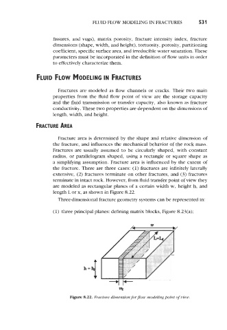
are modeled as rectangular planes of a certain width w, height h, and
length L or x, as shown in Figure 8.22.
Three-dimensional fracture geometry systems can be represented in:
(1) three principal planes: defining matrix blocks, Figure 8.23(a);
Hk
Figure 8.22. Fracture dimension for flow modeling point of view.