
Page 242 - Phase Space Optics Fundamentals and Applications
P. 242
Radiometry, Wave Optics, and Spatial Coherence 223
Q
S 0 s 1
d 0 d
s 2
Δ
Source Two-slit Observation
plane plane
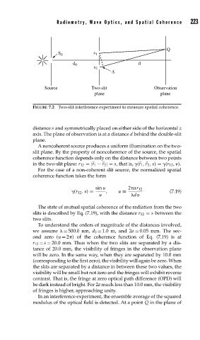
FIGURE 7.2 Two-slit interference experiment to measure spatial coherence.
distance s and symmetrically placed on either side of the horizontal z
axis. The plane of observation is at a distance d behind the double-slit
plane.
A noncoherent source produces a uniform illumination on the two-
slit plane. By the property of noncoherence of the source, the spatial
coherence function depends only on the distance between two points
in the two-slit plane: r 12 =| r 1 − r 2 |= s, that is, ( r 1 , r 2 , ) = (r 12 , ).
For the case of a non-coherent slit source, the normalized spatial
coherence function takes the form
sin u 2 ar 12
(r 12 , ) = , u ≡ (7.19)
u do
The state of mutual spatial coherence of the radiation from the two
slits is described by Eq. (7.19), with the distance r 12 = s between the
two slits.
To understand the orders of magnitude of the distances involved,
we assume = 500.0 nm, d 0 = 1.0 m, and 2a = 0.05 mm. The sec-
ond zero (u = 2 ) of the coherence function of Eq. (7.19) is at
r 12 = s = 20.0 mm. Thus when the two slits are separated by a dis-
tance of 20.0 mm, the visibility of fringes in the observation plane
will be zero. In the same way, when they are separated by 10.0 mm
(corresponding to the first zero), the visibility will again be zero. When
the slits are separated by a distance in between these two values, the
visibility will be small but not zero and the fringes will exhibit reverse
contrast. That is, the fringe at zero optical path difference (OPD) will
be dark instead of bright. For 2a much less than 10.0 mm, the visibility
of fringes is higher, approaching unity.
In an interference experiment, the ensemble average of the squared
modulus of the optical field is detected. At a point Q in the plane of