
Page 18 - Phase-Locked Loops Design, Simulation, and Applications
P. 18
MIXED-SIGNAL PLL BUILDING BLOCKS Ronald E. Best 14
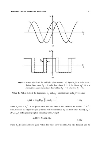
Figure 2.3 Input signals of the multiplier phase detector. (a) Signal u (t) is a sine wave.
1
Dashed line: phase θ = 0; solid line: phase θ > 0. (b) Signal u ′(t) is a
1
1
2
symmetrical square wave signal. Dashed line: θ ′ = 0; solid line: θ ′ > 0.
2 2
When the PLL is locked, the frequencies ω and ω ′ are identical, and u (t) becomes
1 2 d
(2.13)
where θ = θ − θ ′ is the phase error. The first term of this series is the wanted “DC”
1
2
e
term, whereas the higher-frequency terms will be eliminated by the loop filter. Setting K =
d
2U U /π and neglecting higher-frequency terms, we get
10 20
(2.14)
where K is called detector gain. When the phase error is small, the sine function can be
d