
Page 20 - Phase-Locked Loops Design, Simulation, and Applications
P. 20
MIXED-SIGNAL PLL BUILDING BLOCKS Ronald E. Best 15
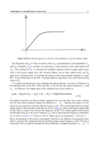
Figure 2.4 Phase-detector gain K as a function of the amplitude U of the reference signal.
d
10
The dimension of K is V/rad. As shown earlier, K is proportional to both amplitudes U
d d 10
and U . Normally, U is constant, so K becomes a linear function of the input signal level
20
d
20
U . This is plotted in Fig. 2.4. Because the multiplier saturates when its output signal comes
10
close to the power supply rails, this function flattens out at large signal levels, and K
d
approaches a limiting value. To conclude the analysis of the four-quadrant multiplier, we state
that—in the locked state of the PLL—the phase detector represents a zero-order block having
a gain of K .
d
To complete the discussion of the multiplier-type phase detector, we look at its behavior in
the unlocked state of the PLL. When the PLL is out of lock, the radian frequencies ω and
1
ω ′ are different. The output signal of the multiplier then can be written as
2
(2.16)
The higher harmonics are almost entirely suppressed by the loop filter, hence there remains
one AC term whose frequency equals the difference ω − ω ′. Because the output is an AC
1 2
signal, we are tempted to conclude that its average is zero. This would imply that the average
output signal of the loop filter would also be zero (cf. Fig. 2.1). This would make it impossible
for the loop to acquire lock because the frequency of the VCO output signal would remain
permanently hung up at its center frequency ω , with a superimposed frequency modulation.
0
As we will see in Sec. 3.9.3, however, the AC signal u (t) is an asymmetric “sine wave”—
d
that is, the durations of the positive and negative half waves are different. Consequently, there
will be a nonzero DC component that will pull the average output frequency of the VCO up or
down until lock is acquired, provided the initial difference of radian frequencies ω − ω ′ is
1 2