
Page 24 - Phase-Locked Loops Design, Simulation, and Applications
P. 24
MIXED-SIGNAL PLL BUILDING BLOCKS Ronald E. Best 17
for different phase errors θ . At zero phase error, the signals u and u ′ are out of phase by
e 1 2
exactly 90°, as shown in Fig. 2.6a. Then the output signal u is a square wave whose
d
frequency is twice the reference frequency; the duty cycle of the u signal is exactly 50
d
percent. Because the high-frequency component of this signal will be filtered out by the loop
filter, we consider only the average value of u , as shown by the dashed line in Fig. 2.6a. The
d
average value (denoted ) is the arithmetic mean of the two logical levels; if the EXOR is
powered from an asymmetrical 5-V power supply, , will be approximately 2.5 V. This
voltage level is considered the quiescent point of the EXOR and will be denoted as = 0
from now on. When the output signal u ′ lags the reference signal u , the phase error θ
2
e
1
becomes positive by definition (this case is shown in Fig. 2.6b). Now the duty cycle of u
d
becomes larger than 50 percent—in other words, the average value of u is considered
d
positive, as shown by the dashed line in the u waveform. Clearly, the mean of u reaches its
d
d
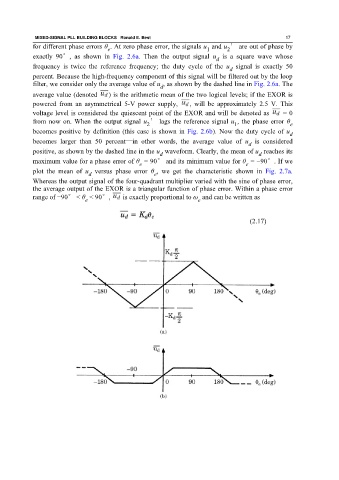
maximum value for a phase error of θ = 90° and its minimum value for θ = −90°. If we
e e
plot the mean of u versus phase error θ , we get the characteristic shown in Fig. 2.7a.
d
e
Whereas the output signal of the four-quadrant multiplier varied with the sine of phase error,
the average output of the EXOR is a triangular function of phase error. Within a phase error
range of −90° < θ < 90°, is exactly proportional to ω and can be written as
e e
(2.17)