
Page 26 - Phase-Locked Loops Design, Simulation, and Applications
P. 26
MIXED-SIGNAL PLL BUILDING BLOCKS Ronald E. Best 18
In the case of the EXOR phase detector, the phase detector gain K is constant. When the
d
supply voltages of the EXOR are U and 0, respectively, and when we assume that the logic
B
levels are U and 0, K is given by
B d
(2.18)
When the output signal of the EXOR does not reach the supply rails but rather saturates at
some higher level U sat+ (in the high state) and some lower level U sat− (in the low state), K
d
must be calculated from
(2.19)
Like the four-quadrant multiplier, the EXOR phase detector can maintain phase tracking
when the phase error is confined to the range
The performance of the EXOR phase detector becomes severely impaired if the signals u
1
and u ′ become asymmetrical. If this happens, the output signal gets clipped at some
2
intermediate level, as shown by Fig. 2.7b. This reduces the loop gain of the PLL and results in
smaller lock range, pull-out range, and so on.
It is important to also look at the performance of the EXOR phase detector in the unlocked
state of the PLL, as we did in the case of the multiplier phase detector. When the PLL is out of
lock, the radian frequencies ω and ω ′ are different. The output signal of the EXOR then
2
1
contains an AC term whose fundamental radian frequency is the difference ω − ω ′, the
1 2
higher harmonics of which will be filtered out by the loop filter. The EXOR therefore
performs very similar to the multiplier phase detector—in other words, the pull-in process
becomes slow, and acquisition is only realized when the difference ω and ω ′ is less than
1 2
the pull-in frequency Δω . This will be discussed in more detail in Sec. 3.9.3.
P
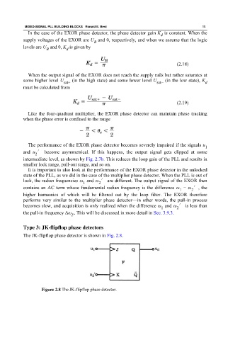
Type 3: JK-flipflop phase detectors
The JK-flipflop phase detector is shown in Fig. 2.8.
Figure 2.8 The JK-flipflop phase detector.