
Page 29 - Phase-Locked Loops Design, Simulation, and Applications
P. 29
MIXED-SIGNAL PLL BUILDING BLOCKS Ronald E. Best 21
error. Because the PFD “knows” at all times whether the frequency of input signal u (t) is
1
higher or lower than the frequency of (scaled-down) output signal u ′(t), it allows the PLL to
2
get locked in the most adverse situations—that is, for arbitrarily large frequency offsets
between the two input signals. Two different types of PFDs are in use today: PFDs with
voltage output and PFDs with current output. The latter is often referred to as “charge
pump.” Besides its large benefits, the PFD with voltage output has a serious problem called
“backlash.” The backlash phenomenon leads to undesired spurious frequencies (commonly
referred to as “spurs”) in the output signal of frequency synthesizers (this will be discussed
in more detail in Sec. 6.7.3). The backlash problem can be avoided when PFDs with current
output are used. This is the reason why the PFD with current output is preferred today in most
applications. We start the discussion of PFDs with the voltage output PFD.
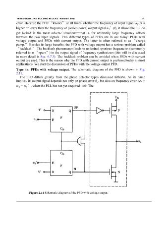
Type 4a: PFDs with voltage output. The schematic diagram of the PFD is shown in Fig.
2.11.
The PFD differs greatly from the phase detector types discussed hitherto. As its name
implies, its output signal depends not only on phase error θ , but also on frequency error Δω =
e
ω − ω ′, when the PLL has not yet acquired lock. The
1
2
Figure 2.11 Schematic diagram of the PFD with voltage output.