
Page 27 - Phase-Locked Loops Design, Simulation, and Applications
P. 27
MIXED-SIGNAL PLL BUILDING BLOCKS Ronald E. Best 19
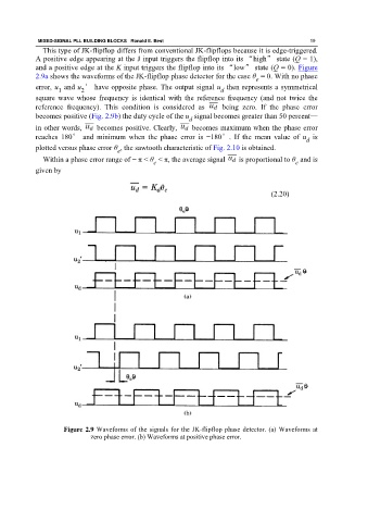
This type of JK-flipflop differs from conventional JK-flipflops because it is edge-triggered.
A positive edge appearing at the J input triggers the flipflop into its “high” state (Q = 1),
and a positive edge at the K input triggers the flipflop into its “low” state (Q = 0). Figure
2.9a shows the waveforms of the JK-flipflop phase detector for the case θ = 0. With no phase
e
error, u and u ′ have opposite phase. The output signal u then represents a symmetrical
1 2 d
square wave whose frequency is identical with the reference frequency (and not twice the
reference frequency). This condition is considered as being zero. If the phase error
becomes positive (Fig. 2.9b) the duty cycle of the u signal becomes greater than 50 percent—
d
in other words, becomes positive. Clearly, becomes maximum when the phase error
reaches 180° and minimum when the phase error is −180°. If the mean value of u is
d
plotted versus phase error θ , the sawtooth characteristic of Fig. 2.10 is obtained.
e
Within a phase error range of − π < θ < π, the average signal is proportional to θ and is
e
e
given by
(2.20)
Figure 2.9 Waveforms of the signals for the JK-flipflop phase detector. (a) Waveforms at
zero phase error. (b) Waveforms at positive phase error.