
Page 30 - Phase-Locked Loops Design, Simulation, and Applications
P. 30
MIXED-SIGNAL PLL BUILDING BLOCKS Ronald E. Best 22
PFD is built from two D-flipflops, whose outputs are denoted “UP” and “DN” (down),
respectively. The PFD can be in one of four states:
■ UP = 0, DN = 0
■ UP = 1, DN = 0
■ UP = 0, DN = 1
■ UP = 1, DN = 1
The fourth state is inhibited, however, by an additional AND gate. Whenever both flipflops
are in the 1 state, a logic “high” level appears at their CD (“clear direct”) inputs, which
resets both flipflops. Consequently, the device acts as a tristable device (“triflop”). We
assign the symbols −1, 0, and 1 to these three states:
■ DN = 1, UP → 0 : state = −1
■ UP = 0, DN → 0 : state = 0
■ UP = 1, DN → 0 : state = 1
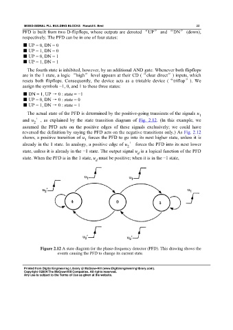
The actual state of the PFD is determined by the positive-going transients of the signals u
1
and u ′, as explained by the state transition diagram of Fig. 2.12. (In this example, we
2
assumed the PFD acts on the positive edges of these signals exclusively; we could have
reversed the definition by saying the PFD acts on the negative transitions only.) As Fig. 2.12
shows, a positive transition of u forces the PFD to go into its next higher state, unless it is
1
already in the 1 state. In analogy, a positive edge of u ′ forces the PFD into its next lower
2
state, unless it is already in the −1 state. The output signal u is a logical function of the PFD
d
state. When the PFD is in the 1 state, u must be positive; when it is in the −1 state,
d
Figure 2.12 A state diagram for the phase-frequency detector (PFD). This drawing shows the
events causing the PFD to change its current state.
Printed from Digital Engineering Library @ McGraw-Hill (www.Digitalengineeringlibrary.com).
Copyright ©2004 The McGraw-Hill Companies. All rights reserved.
Any use is subject to the Terms of Use as given at the website.