
Page 35 - Phase-Locked Loops Design, Simulation, and Applications
P. 35
MIXED-SIGNAL PLL BUILDING BLOCKS Ronald E. Best 25
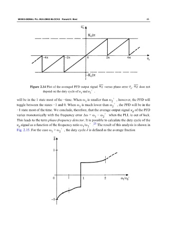
Figure 2.14 Plot of the averaged PFD output signal versus phase error θ . does not
e
depend on the duty cycle of u and u ′.
1
2
will be in the 1 state most of the −time. When ω is smaller than ω ′, however, the PFD will
2
1
toggle between the states −1 and 0. When ω is much lower than ω ′, the PFD will be in the
1 2
−1 state most of the time. We conclude, therefore, that the average output signal u of the PFD
d
varies monotonically with the frequency error Δω = ω − ω ′ when the PLL is out of lock.
1 2
This leads to the term phase-frequency detector. It is possible to calculate the duty cycle of the
23
u signal as a function of the frequency ratio ω /ω ′. The result of this analysis is shown in
1
d
2
Fig. 2.15. For the case ω > ω ′, the duty cycle δ is defined as the average fraction
1 2