
Page 37 - Phase-Locked Loops Design, Simulation, and Applications
P. 37
MIXED-SIGNAL PLL BUILDING BLOCKS Ronald E. Best 26
of time the PFD is in the 1 state; for ω < ω ′, δ is by definition minus the average fraction
1 2
of time the PFD is in the −1 state. As expected, δ approaches 1 when ω >> ω ′, and −1
2
1
when ω << ω ′. Furthermore, δ is nearly 0.5 when ω is greater than ω ′ but both
1 2 1 2
frequencies are close together, and δ is nearly −0.5 when ω is lower than ω ′ but both
1
2
frequencies are close together. This property will greatly simplify the determination of the
pull-in range (Sec. 3.9.3).
It must be emphasized that no such characteristic (see Fig. 2.15) can be defined for the
EXOR and for the JK-flipflop. Because the output signal of the PFD depends on phase
error in the locked state of the PLL and on the frequency error in the unlocked state, a PLL
which uses the PFD will lock under any condition, irrespective of the type of loop filter used.
For this reason, the PFD is the preferred phase detector in PLLs.
Type 4b: PFDs with concurrent output (charge pump). Another benefit of the PFD with
voltage output is worth mentioning. In the vast majority of applications, passive lead-lag loop
filters are used when the PFD serves as phase detector. When none of the MOS transistors is
conducting (refer to Fig. 2.11), the output of the PFD is in the high impedance (hi-Z) state.
When the PLL is locked, this is the case most of the time. Assume now that the loop filter in
Fig. 2.17a is connected with the PFD output. During intervals where the PFD is in the hi-Z
state, capacitor C cannot discharge. Hence, the passive filter behaves like a true integrator
1
when driven from a three-state source. It is therefore unnecessary to use the more complex
active filters, as described in Sec. 2.5.
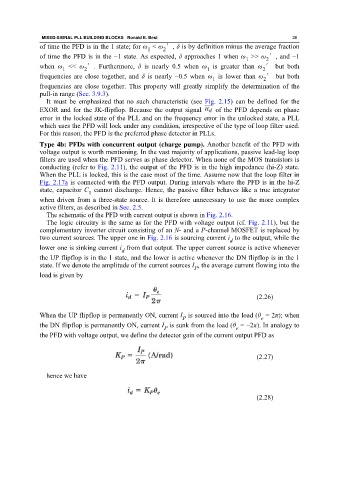
The schematic of the PFD with current output is shown in Fig. 2.16.
The logic circuitry is the same as for the PFD with voltage output (cf. Fig. 2.11), but the
complementary inverter circuit consisting of an N- and a P-channel MOSFET is replaced by
two current sources. The upper one in Fig. 2.16 is sourcing current i to the output, while the
d
lower one is sinking current i from that output. The upper current source is active whenever
d
the UP flipflop is in the 1 state, and the lower is active whenever the DN flipflop is in the 1
state. If we denote the amplitude of the current sources I , the average current flowing into the
P
load is given by
(2.26)
When the UP flipflop is permanently ON, current I is sourced into the load (θ = 2π); when
e
P
the DN flipflop is permanently ON, current I is sunk from the load (θ = −2π). In analogy to
P e
the PFD with voltage output, we define the detector gain of the current output PFD as
(2.27)
hence we have
(2.28)