
Page 236 - Phase-Locked Loops Design, Simulation, and Applications
P. 236
MIXED-SIGNAL PLL APPLICATIONS PART 1: INTEGER-N FREQUENCY
SYNTHESIZERS Ronald E. Best 142
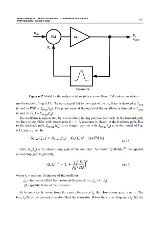
Figure 6.17 Model for the analysis of phase jitter in an oscillator (PM = phase modulator).
use the model of Fig. 6.17. The noise signal fed to the input of the oscillator is denoted as θ
n,in
(f ). The phase noise at the output of the oscillator is denoted as θ
(t) and its PSD is S θθ,in m n,ref
(t) and its PSD is S (f ).
θθ,ref m
The oscillator is represented by a closed loop having positive feedback. In the forward path,
we have an amplifier with power gain G = 1. A resonator is placed in the feedback path. Due
to the feedback path, S (f ) is no longer identical with S (f ) as in the model of Fig.
θθ,ref m θθ,in m
6.15, but is given by
(6.13)
48
Here, G (f ) is the closed-loop gain of the oscillator. As shown by Rohde, the squared
n m
closed-loop gain is given by
(6.14)
where f = resonant frequency of the oscillator
0
f = frequency offset from resonant frequency (i.e. f = f − f )
0
m
m
Q = quality factor of the resonator
At frequencies far away from the carrier frequency f , the closed-loop gain is unity. The
0
term f /2Q is the one-sided bandwidth of the resonator. Below the corner frequency f /2Q, the
0 0