
Page 245 - Phase-Locked Loops Design, Simulation, and Applications
P. 245
MIXED-SIGNAL PLL APPLICATIONS PART 1: INTEGER-N FREQUENCY
SYNTHESIZERS Ronald E. Best 146
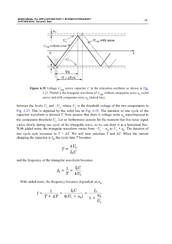
Figure 6.19 Voltage U cap across capacitor C in the relaxation oscillator as shown in Fig.
2.23. Plotted is the triangular waveform of U cap without comparator noise u (solid
n
curve) and with comparator noise u (dotted line).
n
between the levels U and −U , where U is the threshold voltage of the two comparators in
c c c
Fig. 2.23. This is depicted by the solid line in Fig. 6.19. The duration of one cycle of the
capacitor waveform is denoted T. Now assume that there is voltage noise u superimposed to
n
the comparator threshold U . Let us furthermore assume for the moment that this noise signal
c
varies slowly during one cycle of the triangular wave, so we can draw it as a horizontal line.
With added noise, the triangular waveform varies from −U − u to U + u The duration of
c n c n.
one cycle now increases to T + ΔT. We will now calculate T and ΔT. When the current
charging the capacitor is I , the cycle time T becomes
0
and the frequency of the triangular waveform becomes
With added noise, the frequency becomes dependent on u
n