
Page 315 - Phase-Locked Loops Design, Simulation, and Applications
P. 315
MIXED-SIGNAL PLL APPLICATIONS PART 2: FRACTIONAL-N FREQUENCY
SYNTHESIZERS Ronald E. Best 185
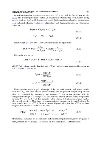
Two of many possible structures are shown here. Let’s start with the first of these (cf. Fig.
7.21a). The dynamic performance of this ΣΔ modulator is determined by two IIR filters having
transfer functions L (z) and L (z), respectively. In this figure, the quantizer has been replaced
0 1
by its mathematical model (cf. Fig. 7.5c). From this block diagram, the following relations can
be derived:
(7.25a)
(7.25b)
Substituting Eq. (7.25b) into (7.25a) yields (after some manipulations)
(7.26)
This can be rewritten as
(7.27)
with STF(z) = signal transfer function, and NTF(z) = noise transfer function. By comparing
Eqs. (7.26) and (7.27), we get
(7.28a)
(7.28b)
These equations reveal a great advantage of the new configuration: both signal transfer
function STF(z) and noise transfer function NTF(z) can be specified independently of each
other. As explained by Norsworthy and coauthors, 55 this is not possible with the
configurations of Figs. 7.14 through 7.16; here, only one transfer function can be prespecified,
normally NTF(z). The STF(z) then depends on the selected STF(z) and sometimes exhibits
adverse peaking effects. There is an important restriction, however, on the specification of the
noise transfer function NTF(f). When a suitable highpass filter function NTF(z) has been
designed, this function is available in the form
(7.29)
where num(z) and den(z) are the numerator and denominator polynomials, respectively, and a i
and b are the filter coefficients. The transfer function of the filter L (z) then becomes
1
i