
Page 310 - Phase-Locked Loops Design, Simulation, and Applications
P. 310
MIXED-SIGNAL PLL APPLICATIONS PART 2: FRACTIONAL-N FREQUENCY
SYNTHESIZERS Ronald E. Best 182
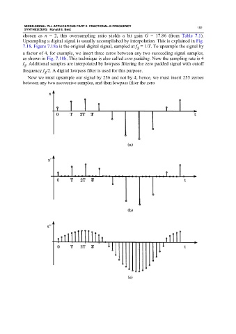
chosen as n = 2, this oversampling ratio yields a bit gain G = 17.86 (from Table 7.1).
Upsampling a digital signal is usually accomplished by interpolation. This is explained in Fig.
7.18. Figure 7.18a is the original digital signal, sampled at f = 1/T. To upsample the signal by
S
a factor of 4, for example, we insert three zeros between any two succeeding signal samples,
as shown in Fig. 7.18b. This technique is also called zero padding. Now the sampling rate is 4
f . Additional samples are interpolated by lowpass filtering the zero padded signal with cutoff
S
frequency f /2. A digital lowpass filter is used for this purpose.
S
Now we must upsample our signal by 256 and not by 4; hence, we must insert 255 zeroes
between any two successive samples, and then lowpass filter the zero