
Page 308 - Phase-Locked Loops Design, Simulation, and Applications
P. 308
MIXED-SIGNAL PLL APPLICATIONS PART 2: FRACTIONAL-N FREQUENCY
SYNTHESIZERS Ronald E. Best 181
have to be chosen for the ΣΔ ADC, say, the configuration with both feedback and feedforward
paths [cf. Fig. 7.16].) A numerical example of a fourth-order ΣΔ ADC with weighted
feedword summation is given in Norsworthy and coauthors. 55
As mentioned earlier, the error sequence of the quantizer is processed by two filters in
cascade. The first of these is the highpass filter with frequency response NTF(f) that rejects
low frequencies between 0 and the stopband-edge frequency. Frequencies above the stopband-
edge pass through the filter and thus must be removed by the postprocessing digital lowpass
filter, as shown in Figs. 7.14, 7.15, and 7.16. To efficiently reject those higher frequencies, the
cutoff frequency of the digital filter should be chosen to coincide with the stopband-edge
frequency of the highpass filter. The lowpass filter is usually implemented as an FIR filter. It
is sampled at the fast frequency f but the output signal D is read out at the slow sampling rate
F
f , which is lower than f by the factor OSR. Because the transition region of the lowpass filter
F
S
should be narrow in order to sufficiently reject the frequencies above f /2, the length (order) of
S
the FIR filter must be chosen to be large—usually around 100.
Every ΣΔ ADC consists of two parts: an analog portion and a digital one. The integrators
are operating in continuous time, and hence are linear circuits. They can be implemented
either as active RC integrators or as switched capacitor filters (SC).
The ΣΔ D/A converter
One of the first applications of the ΣΔ DAC was in audio CD players. The audio signal on the
CD is encoded with a word length of 16 bits. Data are read out with a sampling rate of 44.1
kHz, which is twice the bandwidth of the audio signal. To play the CD on a linear amplifier,
the digital signal must be converted to analog. Because 16-bit DACs have proven rather
expensive, manufacturers of CD players used ΣΔ DACs built from an extremely simple one-
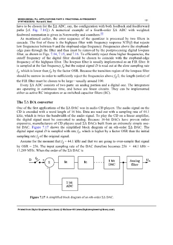
bit DAC. Figure 7.17 shows the simplified block diagram of an nth-order ΣΔ DAC. The
digital input signal D is sampled with rate f , which is higher by a factor OSR than the initial
F
sampling rate f of the original signal.
S
Assume for the moment that f = 44.1 kHz and that we are going to over-sample that signal
S
by OSR = 256. The input sampling rate of the DAC therefore becomes 256 · 44.1 kHz =
11.289 MHz. When the order of the ΣΔ DAC is
Figure 7.17 A simplified block diagram of an nth-order ΣΔ DAC.
Printed from Digital Engineering Library @ McGraw-Hill (www.Digitalengineeringlibrary.com).