
Page 304 - Phase-Locked Loops Design, Simulation, and Applications
P. 304
MIXED-SIGNAL PLL APPLICATIONS PART 2: FRACTIONAL-N FREQUENCY
SYNTHESIZERS Ronald E. Best 179
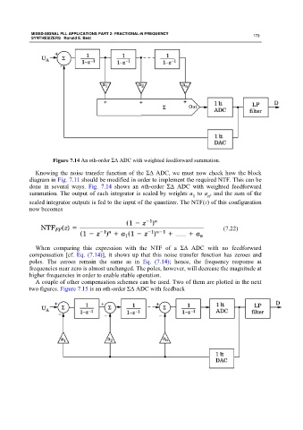
Figure 7.14 An nth-order ΣΔ ADC with weighted feedforward summation.
Knowing the noise transfer function of the ΣΔ ADC, we must now check how the block
diagram in Fig. 7.11 should be modified in order to implement the required NTF. This can be
done in several ways. Fig. 7.14 shows an nth-order ΣΔ ADC with weighted feedforward
summation. The output of each integrator is scaled by weights a to a , and the sum of the
1 n
scaled integrator outputs is fed to the input of the quantizer. The NTF(z) of this configuration
now becomes
(7.22)
When comparing this expression with the NTF of a ΣΔ ADC with no feedforward
compensation [cf. Eq. (7.14)], it shows up that this noise transfer function has zeroes and
poles. The zeroes remain the same as in Eq. (7.14); hence, the frequency response at
frequencies near zero is almost unchanged. The poles, however, will decrease the magnitude at
higher frequencies in order to enable stable operation.
A couple of other compensation schemes can be used. Two of them are plotted in the next
two figures. Figure 7.15 is an nth-order ΣΔ ADC with feedback