
Page 302 - Phase-Locked Loops Design, Simulation, and Applications
P. 302
MIXED-SIGNAL PLL APPLICATIONS PART 2: FRACTIONAL-N FREQUENCY
SYNTHESIZERS Ronald E. Best 178
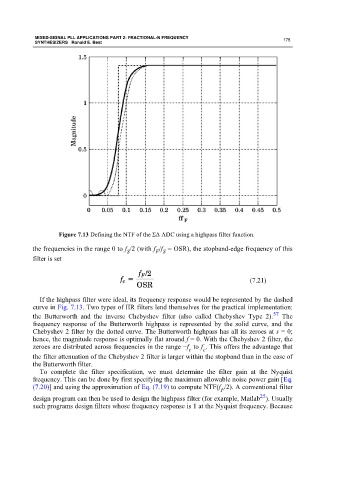
Figure 7.13 Defining the NTF of the ΣΔ ADC using a highpass filter function.
the frequencies in the range 0 to f /2 (with f /f = OSR), the stopband-edge frequency of this
F S
S
filter is set
(7.21)
If the highpass filter were ideal, its frequency response would be represented by the dashed
curve in Fig. 7.13. Two types of IIR filters lend themselves for the practical implementation:
57
the Butterworth and the inverse Chebyshev filter (also called Chebyshev Type 2). The
frequency response of the Butterworth highpass is represented by the solid curve, and the
Chebyshev 2 filter by the dotted curve. The Butterworth highpass has all its zeroes at s = 0;
hence, the magnitude response is optimally flat around f = 0. With the Chebyshev 2 filter, the
zeroes are distributed across frequencies in the range −f to f . This offers the advantage that
c
c
the filter attenuation of the Chebyshev 2 filter is larger within the stopband than in the case of
the Butterworth filter.
To complete the filter specification, we must determine the filter gain at the Nyquist
frequency. This can be done by first specifying the maximum allowable noise power gain [Eq.
(7.20)] and using the approximation of Eq. (7.19) to compute NTF(f /2). A conventional filter
F
25
design program can then be used to design the highpass filter (for example, Matlab ). Usually
such programs design filters whose frequency response is 1 at the Nyquist frequency. Because