
Page 298 - Phase-Locked Loops Design, Simulation, and Applications
P. 298
MIXED-SIGNAL PLL APPLICATIONS PART 2: FRACTIONAL-N FREQUENCY
SYNTHESIZERS Ronald E. Best 176
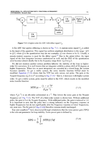
Figure 7.11 A higher-order ΣΔ ADC with dither signal U .
d
A ΣΔ ADC that applies dithering is shown in Fig. 7.11. A random noise signal U is added
d
to the input of the quantizer. This signal has uniform amplitude distribution in the range −Q/2
to Q/2, where Q is the quantization step (in our examples, Q was chosen to be 1). Usually, a
55
pseudo-random sequence is used for the dither signal. Due to the added dither, the input
signal of the first integrator becomes randomized as well, and the PSD of the quantization
error becomes almost ideally flat in the frequency range from −f /2 to f /2.
F
F
We did not mention another serious problem hitherto: the stability of the loop in higher-
order ΣΔ converters. It is well known that an integrator exhibits a phase shift of 90 degrees at
higher frequencies. When two or more integrators are cascaded in a closed loop, the system
becomes unstable. To get a stable system, the noise transfer function NTF(f) must be
modified. Equation (7.14) shows that the NTF has only zeroes, not poles. The gain at the
n
Nyquist frequency (f /2) is 2 according to Eq. (7.15)—that is, it increases with higher system
F
order. To get a stable system, poles must be added to the NTF, which results in the modified
noise transfer function
(7.17)
−1
−1
where P (z ) is an nth-order polynomial in z . This lowers the noise gain at the Nyquist
n
frequency (cf. Fig. 7.12). The NTF of a third-order system is shown here. Without additional
poles, the gain is 8 at the Nyquist frequency. With additional poles, the gain is reduced to 1.4.
It is important to note that the poles have a strong influence on the frequency response at
higher frequencies but do not significantly alter the frequency response at lower frequencies,
say, near zero. The bit gain [cf. Eq. (7.16)] therefore remains nearly unchanged.
56
Kuo and coauthors have discovered through simulations that the noise power gain (NPG)
is the relevant parameter for loop stability. Noise power gain is defined by
(7.18)