
Page 296 - Phase-Locked Loops Design, Simulation, and Applications
P. 296
MIXED-SIGNAL PLL APPLICATIONS PART 2: FRACTIONAL-N FREQUENCY
SYNTHESIZERS Ronald E. Best 175
The analog input signal U is simply delayed by n sampling intervals, and the error
A
sequence is passed through n differentiators in cascade. The frequency response NTF(f) is
therefore given by
(7.15)
When comparing the frequency response of the nth-order ΣΔ ADC with the frequency
response of the first-order ADC, it is easily seen that the magnitude response at frequencies
near zero becomes flatter the higher the order of the ΣΔ converter that is chosen. At low
frequencies, the sine function can be replaced by its argument; hence, for the first-order
2
n
converter, NTF(f) varies with f, for the second order with f and for the nth-order with f . For
higher-order ΣΔ ADCs, the power density spectrum of the error sequence gets much more
suppressed than for the first-order ADC; thus, much larger bit gains can be realized with
relatively low oversampling ratios. The bit gain of the nth-order ΣΔ ADC can be shown to
be 55
(7.16)
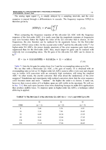
Table 7.1 lists the bit gain for orders from 1 to 3 and for oversampling ratios up to 256.
We see that with a third-order ΣΔ ADC, a bit gain of nearly 14 is obtained with an
oversampling ratio as low as 32. Higher-order ΣΔ ADCs seem to offer a very easy and elegant
way to realize A/D converters with an extremely high resolution, still using the simplest
ADC—in other words, the one-bit converter. But what about the randomness of the error
sequence? Simulations and experiments with realized converters show that the error sequence
e(nT) becomes more and more “random” the higher the order n is chosen. It turns out,
however, that even at orders of 6 or higher, spurs are still visible in the spectrum. We will see
in Sec. 7.4.2 that such spurs become even more disturbing because in audio D/A applications
they produce audible tones. To suppress spurs in higher-order ΣΔ ADCs, a technique called
dithering is applied.
TABLE 7.1 The Bit Gain G of the nth-Order ΣΔ ADC for n = 1 to 3, and OSR Up to 256
G G G
OSR (n = 1) (n = 2) (n = 3)
8 3.64 5.36 6.95
16 5.14 7.86 10.45
32 6.64 10.36 13.95
64 8.14 12.86 17.45
128 9.64 15.36 20.95
256 11.14 17.86 24.45