
Page 292 - Phase-Locked Loops Design, Simulation, and Applications
P. 292
MIXED-SIGNAL PLL APPLICATIONS PART 2: FRACTIONAL-N FREQUENCY
SYNTHESIZERS Ronald E. Best 173
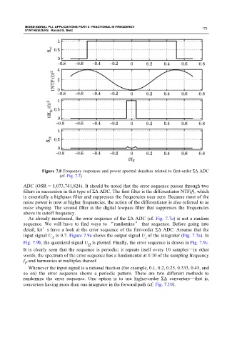
Figure 7.8 Frequency responses and power spectral densities related to first-order ΣΔ ADC
(cf. Fig. 7.7)
ADC (OSR = 1,073,741,824). It should be noted that the error sequence passes through two
filters in succession in this type of ΣΔ ADC. The first filter is the differentiator NTF(f), which
is essentially a highpass filter and suppresses the frequencies near zero. Because most of the
noise power is now at higher frequencies, the action of the differentiator is also referred to as
noise shaping. The second filter is the digital lowpass filter that suppresses the frequencies
above its cutoff frequency.
As already mentioned, the error sequence of the ΣΔ ADC (cf. Fig. 7.7a) is not a random
sequence. We will have to find ways to “randomize” that sequence. Before going into
detail, let’s have a look at the error sequence of the first-order ΣΔ ADC. Assume that the
input signal U is 0.7. Figure 7.9a shows the output signal U of the integrator (Fig. 7.7a). In
A i
Fig. 7.9b, the quantized signal U is plotted. Finally, the error sequence is drawn in Fig. 7.9c.
Q
It is clearly seen that the sequence is periodic; it repeats itself every 10 samples—in other
words, the spectrum of the error sequence has a fundamental at 1/10 of the sampling frequency
f and harmonics at multiples thereof.
F
Whenever the input signal is a rational fraction (for example, 0.1, 0.2, 0.25, 0.333, 0.45, and
so on) the error sequence shows a periodic pattern. There are two different methods to
randomize the error sequence. One option is to use higher-order ΣΔ converters—that is,
converters having more than one integrator in the forward path (cf. Fig. 7.10).