
Page 167 - Photodetection and Measurement - Maximizing Performance in Optical Systems
P. 167
Control of Ambient Light
160 Chapter Seven
particles moving at 1m/s contribute to the 3.2MHz signal. All 1.1m/s particles
give a 3.5MHz signal and so on. Most importantly, the stationary wall does not
give appreciable modulation, and so its scattered light signal can be electroni-
cally separated from that of the moving particles.
The backscatter geometry of Fig. 7.17b is restricting for some applications.
An alternative is to form an interference pattern in the intersection of two
beams. As a particle moves through the pattern, it scatters a chirp of light with
a characteristic frequency given by the number of fringes-per-second inter-
cepted. In this case the detector can be placed almost anywhere where it can
pick up adequate signal. The ability to tailor the fringe spacing through adjust-
ment of the intersection angle allows it to be optimized for particles of a par-
ticular size. The chirp frequency gives the component of particle velocity normal
to the fringes, while the visibility of the pattern depends on of the particle size.
Figure 7.17c shows an unbalanced interferometer, in which the two arms have
very different lengths. This is not a problem for a source of greater coherence
length, and high contrast fringes will be formed throughout the intersection
volume. On the other hand, if a very short coherence length source such as an
LED were used, no fringes would be seen in the diagram. This characteristic
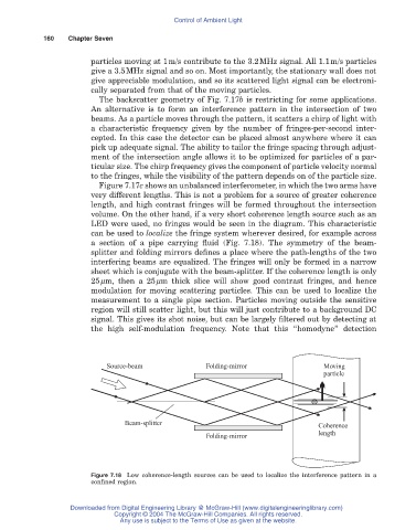
can be used to localize the fringe system wherever desired, for example across
a section of a pipe carrying fluid (Fig. 7.18). The symmetry of the beam-
splitter and folding mirrors defines a place where the path-lengths of the two
interfering beams are equalized. The fringes will only be formed in a narrow
sheet which is conjugate with the beam-splitter. If the coherence length is only
25mm, then a 25mm thick slice will show good contrast fringes, and hence
modulation for moving scattering particles. This can be used to localize the
measurement to a single pipe section. Particles moving outside the sensitive
region will still scatter light, but this will just contribute to a background DC
signal. This gives its shot noise, but can be largely filtered out by detecting at
the high self-modulation frequency. Note that this “homodyne” detection
Source-beam Folding-mirror Moving
particle
Beam-splitter
Coherence
length
Folding-mirror
Figure 7.18 Low coherence-length sources can be used to localize the interference pattern in a
confined region.
Downloaded from Digital Engineering Library @ McGraw-Hill (www.digitalengineeringlibrary.com)
Copyright © 2004 The McGraw-Hill Companies. All rights reserved.
Any use is subject to the Terms of Use as given at the website.