
Page 171 - Photodetection and Measurement - Maximizing Performance in Optical Systems
P. 171
Stability and Tempco Issues
164 Chapter Eight
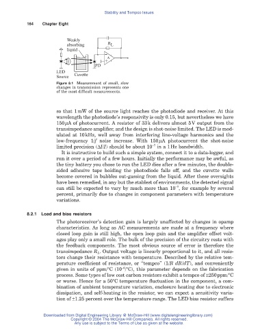
Weakly
absorbing R L
liquid
+ A
-
PD
LED
Source Cuvette
Figure 8.1 Measurement of small, slow
changes in transmission represents one
of the most difficult measurements.
so that 1mW of the source light reaches the photodiode and receiver. At this
wavelength the photodiode’s responsivity is only 0.15, but nevertheless we have
150mA of photocurrent. A resistor of 33k delivers almost 5V output from the
transimpedance amplifier, and the design is shot-noise limited. The LED is mod-
ulated at 10kHz, well away from interfering line-voltage harmonics and the
low-frequency 1/f noise increase. With 150mA photocurrent the shot-noise
-7
limited precision (DI/I) should be about 10 in a 1Hz bandwidth.
It is instructive to build such a simple system, connect it to a data-logger, and
run it over a period of a few hours. Initially the performance may be awful, as
the tiny battery you chose to run the LED dies after a few minutes, the double-
sided adhesive tape holding the photodiode falls off, and the cuvette walls
become covered in bubbles out-gassing from the liquid. After these oversights
have been remedied, in any but the stablest of environments, the detected signal
-7
can still be expected to vary by much more than 10 , for example by several
percent, primarily due to changes in component parameters with temperature
variations.
8.2.1 Load and bias resistors
The photoreceiver’s detection gain is largely unaffected by changes in opamp
characteristics. As long as AC measurements are made at a frequency where
closed loop gain is still high, the open loop gain and the amplifier offset volt-
ages play only a small role. The bulk of the precision of the circuitry rests with
the feedback components. The most obvious source of error is therefore the
transimpedance R L. Output voltage is linearly proportional to it, and all resis-
tors change their resistance with temperature. Described by the relative tem-
perature coefficient of resistance, or “tempco” (1/RdR/dT), and conveniently
-6
given in units of ppm/°C (10 /°C), this parameter depends on the fabrication
process. Some types of low cost carbon resistors exhibit a tempco of ±250ppm/°C
or worse. Hence for a 50°C temperature fluctuation in the component, a com-
bination of ambient temperature variation, enclosure heating due to electronic
dissipation, and self-heating in the resistor, we can expect a sensitivity varia-
tion of ±1.25 percent over the temperature range. The LED bias resistor suffers
Downloaded from Digital Engineering Library @ McGraw-Hill (www.digitalengineeringlibrary.com)
Copyright © 2004 The McGraw-Hill Companies. All rights reserved.
Any use is subject to the Terms of Use as given at the website.