
Page 223 - Photodetection and Measurement - Maximizing Performance in Optical Systems
P. 223
Measurand Modulation
216 Chapter Ten
(a) Source modulation
Lock-in amplifier
1 1-d RC Time
Multiplier
d Constant Voltage
Source I p Display
G
1-d
Signal
0
Time
(b) Absorption modulation
Lock-in amplifier
1 1-d RC Time
Multiplier
d Constant Voltage
Source I p Display
G
1
Signal 1-d
Time
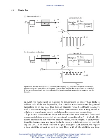
Figure 10.2 Source modulation (a) does little to improve the weak absorbance measurement,
as the minimum detectable transmission change is defined by the source/detection stability.
If the absorbance itself can be modulated (b), much smaller transmission changes can be
detected.
an LED, we might need to stabilize its temperature to better than 1mK to
achieve this. While not impossible, this is tricky in an instrument for general
laboratory or on-line use. This level of stability would be difficult to achieve
with a conventional optical transmission measurement over a long period. A
solution is to exchange source modulation for measurand modulation.
Figure 10.2 shows schematic optical transmission measurements. Our usual
source-modulation scheme (a) gives a signal proportional to 1 - d pk-pk. The
source modulation has removed baseline errors, but the signal is still propor-
tional to channel gain, and in particular to the source intensity, gravely restrict-
ing the LOD. If we want to detect a signal change of 0.01 percent, we require
a total stability at least as good as that. Even with all the stability and tem-
Downloaded from Digital Engineering Library @ McGraw-Hill (www.digitalengineeringlibrary.com)
Copyright © 2004 The McGraw-Hill Companies. All rights reserved.
Any use is subject to the Terms of Use as given at the website.