
Page 124 - Photonics Essentials an introduction with experiments
P. 124
Light-Emitting Diodes
118 Photonic Devices
tion. Precise analysis is complicated since the actual path of the light
depends on where it is emitted within the LED structure, as illustrat-
ed in Fig. 6.9. This technique is widely used in LED fabrication. This
modification does not help to increase the amount of light emitted.
However, it gives an important clue about how to proceed.
The application of Fresnel’s equation (Eq. 6.11) shows that 68% of
the light that is incident perpendicular to the surface of an LED made
from materials with a strong index contrast relative to air, (i.e., 3.3 to
1), can escape. One way to improve the percentage of light that can es-
cape from an LED is to make the angle of incidence look more like 90°
for all the light. One could machine the surface of the LED so it looks
like a hemisphere. This is a complicated and expensive procedure.
There is a simpler version of this idea that is just as effective, and
much less expensive to implement.
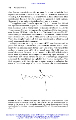
A highly textured emitting surface of an LED, one characterized by
peaks and valleys, is rather the opposite of the smooth planar inter-
face between the semiconductor and air. The optical reflection of this
surface is much more difficult to model using Eq. 6.11 than the
smooth interface. However, as can be seen in Fig 6.10, this interface
offers some significant advantages for improving light emission. To
understand how such a surface can be used to advantage, imagine for
a moment the possibilities for a photon that reaches the surface. The
first encounter with the interface probably results in reflection be-
cause of the oblique angle of incidence. However, the photon is not re-
Figure 6.10. This is a schematic diagram of a highly textured emitting surface. Light
intercepting the surface from below is initially reflected, but will pass through the in-
terface on the second or third bounce because it lies inside the escape cone. For the
semiconductor/air interface with an index contrast of 3.4 to 1, this cone has an angle of
about 16°.
Downloaded from Digital Engineering Library @ McGraw-Hill (www.digitalengineeringlibrary.com)
Copyright © 2004 The McGraw-Hill Companies. All rights reserved.
Any use is subject to the Terms of Use as given at the website.