
Page 253 - Photonics Essentials an introduction with experiments
P. 253
Experimental Photonics: Device Characterization in the Laboratory
Experimental Photonics: Device Characterization in the Laboratory 247
building a mount for the diode. A transistor socket can be soldered
onto one end of a BNC cable in a few minutes. The cable consists of
two conductors, one for each terminal of the diode. The diode can then
be held in place for measurements by applying a clamp to the cable,
not the device.
b) I–V Measurements Using the Curve Tracer. The curve tracer is the
most reliable instrument you can use to determine which lead con-
nects to the p-side of the diode. This instrument comes in many differ-
ent varieties. A quick reading of the instruction manual will save both
time and burned-out diodes. The initial conditions for measurement
require modest values of voltage—that is –1 volt to +1 volt—and low
values of current—10 microamps full scale. Insert the photodiode into
the socket that you have prepared. The center conductor of the BNC
should be connected to the positive voltage terminal of the curve trac-
er. You will get one of two possible results, as shown in Fig. 11.1.
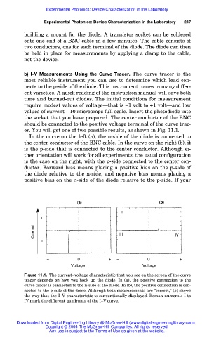
In the curve on the left (a), the n-side of the diode is connected to
the center conductor of the BNC cable. In the curve on the right (b), it
is the p-side that is connected to the center conductor. Although ei-
ther orientation will work for all experiments, the usual configuration
is the case on the right, with the p-side connected to the center con-
ductor. Forward bias means placing a positive bias on the p-side of
the diode relative to the n-side, and negative bias means placing a
positive bias on the n-side of the diode relative to the p-side. If your
II I
+
Current III IV
–
– 0 + – 0 +
Voltage Voltage
Figure 11.1. The current–voltage characteristic that you see on the screen of the curve
tracer depends on how you hook up the diode. In (a), the positive connection to the
curve tracer is connected to the n-side of the diode. In (b), the positive connection is con-
nected to the p-side of the diode. Although both measurements are “correct,” (b) shows
the way that the I–V characteristic is conventionally displayed. Roman numerals I to
IV mark the different quadrants of the I–V curve.
Downloaded from Digital Engineering Library @ McGraw-Hill (www.digitalengineeringlibrary.com)
Copyright © 2004 The McGraw-Hill Companies. All rights reserved.
Any use is subject to the Terms of Use as given at the website.