
Page 248 - Photonics Essentials an introduction with experiments
P. 248
Measurements in Photonics
242 Characterizing Photonic Devices in the Laboratory
Problems
10.1 Measure the basic behavior of a lock-in amplifier. (Equipment
needed: Si photodiode, chopping wheel, lock-in amplifier, visible
light source such as a flashlight. Optional equipment: an oscillo-
scope.)
Prepare a socket for the photodiode by soldering to the socket
two leads that are compatible with the signal entry port of the
lock-in amplifier.
Construct a stable mount for the photodiode socket.
Connect the two leads of the photodiode into the socket.
Plug the socket leads into the signal entry of the lock-in amplifier.
Place the chopping wheel between the light source and the pho-
todiode socket. Synchronize the lock-in amplifier to the chop-
ping wheel.
Observe: Phase at which the maximum signal is detected
Dependence of the phase on the movement of the light
source
Effect of the chopping frequency on the measurement
Effect of other external light sources
Repeat these observations using the oscilloscope instead of the
lock-in amplifier. Compare the effects of external electrical
and optical signals (and noise!) in the two cases.
10.2 The f-number of a lens is another way of expressing its focusing
angle for parallel light. This is also known as the aperture of the
lens.
(a) Determine this angle for the following cases: f/2, f/5.6, and f/8.
(b) Make a graph showing the angle of aperture as a function of
f-number. Paste a copy of this graph in your lab book.
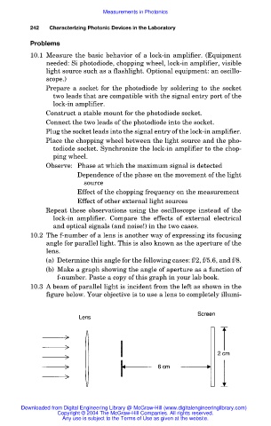
10.3 A beam of parallel light is incident from the left as shown in the
figure below. Your objective is to use a lens to completely illumi-
Downloaded from Digital Engineering Library @ McGraw-Hill (www.digitalengineeringlibrary.com)
Copyright © 2004 The McGraw-Hill Companies. All rights reserved.
Any use is subject to the Terms of Use as given at the website.