
Page 245 - Photonics Essentials an introduction with experiments
P. 245
Measurements in Photonics
Measurements in Photonics 239
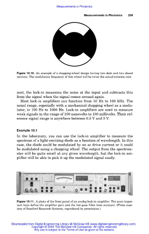
Figure 10.10. An example of a chopping-wheel design having two slots and two closed
sections. The modulation frequency of this wheel will be twice the actual rotation rate.
sent, the lock-in measures the noise at the input and subtracts this
from the signal when the signal comes around again.
Most lock-in amplifiers can function from 10 Hz to 100 kHz. The
usual range, especially with a mechanical chopping wheel as a modu-
lator, is 100 Hz to 1000 Hz. Lock-in amplifiers are used to measure
weak signals in the range of 100 nanovolts to 100 millivolts. Their ref-
erence signal range is anywhere between 0.5 V and 5 V.
Example 10.1
In the laboratory, you can use the lock-in amplifier to measure the
spectrum of a light-emitting diode as a function of wavelength. In this
case, the diode could be modulated by an ac drive current or it could
be modulated using a chopping wheel. The output from the spectrom-
eter will be quite small at any given wavelength, but the lock-in am-
plifier will be able to pick it up the modulated signal easily.
Figure 10.11. A photo of the front panel of an analog lock-in amplifier. The most impor-
tant keys define the amplifier gain and the low-pass filter time constant. (Photo cour-
tesy of Stanford Research Systems, reproduced by permission.)
Downloaded from Digital Engineering Library @ McGraw-Hill (www.digitalengineeringlibrary.com)
Copyright © 2004 The McGraw-Hill Companies. All rights reserved.
Any use is subject to the Terms of Use as given at the website.