
Page 244 - Photonics Essentials an introduction with experiments
P. 244
Measurements in Photonics
238 Characterizing Photonic Devices in the Laboratory
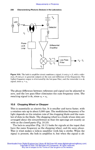
Figure 10.9. The lock-in amplifier circuit combines a signal, A cos( s t + f), with a refer-
ence, B cos( r t), to generate outputs at the sum and difference of the frequencies. The
higher-frequency output is eliminated by the low-pass filter, and the remainder is a dc
signal, since r = s .
The phase difference between reference and signal can be adjusted to
zero, and the low pass filter eliminates the sum frequency term. The
resulting signal is dc, since r = s .
10.8 Chopping Wheel or Chopper
This is essentially an electric fan. It is smaller and turns faster, with
a rotation rate up to about 5,000 rpm. The modulation frequency of he
light depends on the rotation rate of the chopping blade and the num-
ber of slots in the blade. The chopping wheel is a blade whose slots are
arranged about the circumference so that the openings are exactly as
wide as the closed parts (Fig. 10.10).
The lock-in amplifier (Fig. 10.11) looks for signals at the input that
have the same frequency as the chopping wheel, and the same phase.
This is what makes a lock-in amplifier work like a strobe. When the
signal is present, the lock-in amplifies it, but when the signal is ab-
Downloaded from Digital Engineering Library @ McGraw-Hill (www.digitalengineeringlibrary.com)
Copyright © 2004 The McGraw-Hill Companies. All rights reserved.
Any use is subject to the Terms of Use as given at the website.