
Page 280 - Physical Principles of Sedimentary Basin Analysis
P. 280
262 Rheology: fracture and flow
τ τ
τ = μσ
τ τ
2θ 2θ
φ
σ σ σ σ
σ a
σ 3 σ 1 σ b
σ c
(a) (b)
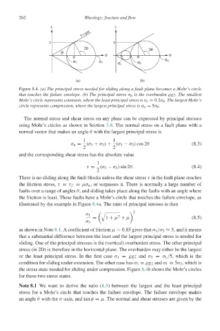
Figure 8.4. (a) The principal stress needed for sliding along a fault plane becomes a Mohr’s circle
that touches the failure envelope. (b) The principal stress σ b is the overburden gz. The smallest
Mohr’s circle represents extension, where the least principal stress is σ c = 0.2σ b . The largest Mohr’s
circle represents compression, where the largest principal stress is σ a = 5σ b .
The normal stress and shear stress on any plane can be expressed by principal stresses
using Mohr’s circles as shown in Section 3.8. The normal stress on a fault plane with a
normal vector that makes an angle θ with the largest principal stress is
1 1
σ n = (σ 1 + σ 3 ) + (σ 1 − σ 3 ) cos 2θ (8.3)
2 2
and the corresponding shear stress has the absolute value
1
τ = (σ 1 − σ 3 ) sin 2θ. (8.4)
2
There is no sliding along the fault blocks unless the shear stress τ in the fault plane reaches
the friction stress, τ = τ f = μσ n , or surpasses it. There is normally a large number of
faults over a range of angles θ, and sliding takes place along the faults with an angle where
the friction is least. These faults have a Mohr’s circle that touches the failure envelope, as
illustrated by the example in Figure 8.4a. The ratio of principal stresses is then
2
!
σ 1 2
= 1 + μ + μ (8.5)
σ 3
as shown in Note 8.1. A coefficient of friction μ = 0.85 gives that σ 1 /σ 3 ≈ 5, and it means
that a substantial difference between the least and the largest principal stress is needed for
sliding. One of the principal stresses is the (vertical) overburden stress. The other principal
stress (in 2D) is therefore in the horizontal plane. The overburden may either be the largest
or the least principal stress. In the first case σ 1 = gz and σ 3 = σ 1 /5, which is the
condition for sliding under extension. The other case has σ 3 = gz and σ 1 = 5σ 3 , which is
the stress state needed for sliding under compression. Figure 8.4b shows the Mohr’s circles
for these two stress states.
Note 8.1 We want to derive the ratio (8.5) between the largest and the least principal
stress for a Mohr’s circle that touches the failure envelope. The failure envelope makes
an angle θ with the σ-axis, and tan φ = μ. The normal and shear stresses are given by the