
Page 45 - Physical chemistry eng
P. 45
22 CHAPTER 2 Heat, Work, Internal Energy, Enthalpy, and the First Law of Thermodynamics
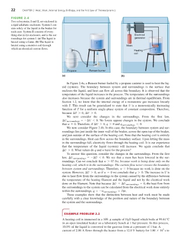
FIGURE 2.4
Two subsystems, I and II, are enclosed in
a rigid adiabatic enclosure. System I con-
sists solely of the liquid in the beaker for
each case. System II consists of every-
thing else in the enclosure, and is the sur- Electrical
roundings for system I. (a) The liquid is generator
heated using a flame. (b) The liquid is
I
heated using a resistive coil through Mass
which an electrical current flows. I
Heating
coil
Propane Bunsen burner
(a) (b)
In Figure 2.4a, a Bunsen burner fueled by a propane canister is used to heat the liq-
uid (system). The boundary between system and surroundings is the surface that
encloses the liquid, and heat can flow all across this boundary. It is observed that the
temperature of the liquid increases in the process. The temperature of the surroundings
also increases because the system and surroundings are in thermal equilibrium. From
Section 1.2, we know that the internal energy of a monatomic gas increases linearly
with T. This result can be generalized to state that U is a monotonically increasing
function of T for a uniform single-phase system of constant composition. Therefore,
because ¢T 7 0 , ¢U 7 0 .
We next consider the changes in the surroundings. From the first law,
¢U surroundings =-¢U 6 0 . No forces oppose changes in the system. We conclude
that w = 0 . Therefore, if ¢U 7 0 , q 7 0 and q surroundings 6 . 0
We now consider Figure 2.4b. In this case, the boundary between system and sur-
roundings lies just inside the inner wall of the beaker, across the open top of the beaker,
and just outside of the surface of the heating coil. Note that the heating coil is entirely
in the surroundings. Heat can flow across the boundary surface. Upon letting the mass
in the surroundings fall, electricity flows through the heating coil. It is our experience
that the temperature of the liquid (system) will increase. We again conclude that
¢U 7 0 . What values do q and w have for the process?
To answer this question, consider the changes in the surroundings. From the first
law, ¢U surroundings =-¢U 6 0 . We see that a mass has been lowered in the sur-
roundings. Can we conclude that w 7 0 ? No, because work is being done only on the
heating coil, which is in the surroundings. The current flow never crosses the boundary
between system and surroundings. Therefore, w = 0 because no work is done on the
system. However, ¢U 7 0 , so if w = 0 we conclude that q 7 0 . The increase in U is
due to heat flow from the surroundings to the system caused by the difference between
the temperature of the heating filament and the liquid and not by the electrical work
done on the filament. Note that because ¢U +¢U surroundings = 0 , the heat flow from
the surroundings to the system can be calculated from the electrical work done entirely
within the surroundings, q =-w surroundings = Ift .
These examples show that the distinction between heat and work must be made
carefully with a clear knowledge of the position and nature of the boundary between
the system and the surroundings.
EXAMPLE PROBLEM 2.2
A heating coil is immersed in a 100. g sample of H O liquid which boils at 99.61°C
2
in an open insulated beaker on a laboratory bench at 1 bar pressure. In this process,
10.0% of the liquid is converted to the gaseous form at a pressure of 1 bar. A
3
current of 2.00 A flows through the heater from a 12.0 V battery for 1.00 * 10 s to