
Page 228 - Pipeline Pigging Technology
P. 228
Pipeline isolation - available options
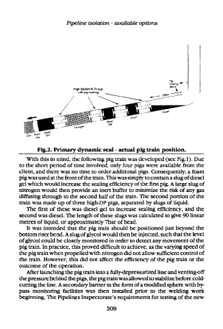
Fig.2. Primary dynamic seal - actual pig train position.
With this in mind, the following pig train was developed (see Fig.l). Due
to the short period of time involved, only four pigs were available from the
client, and there was no time to order additional pigs. Consequently, a foam
pig was used at the front of the train. This was simply to contain a slug of diesel
gel which would increase the sealing efficiency of the first pig. A large slug of
nitrogen would then provide an inert buffer to minimize the risk of any gas
diffusing through to the second half of the train. The second portion of the
train was made up of three high-DP pigs, separated by slugs of liquid.
The first of these was diesel gel to increase sealing efficiency, and the
second was diesel. The length of these slugs was calculated to give 90 linear
metres of liquid, or approximately Tbar of head.
It was intended that the pig train should be positioned just beyond the
bottom riser bend. A slug of glycol would then be injected, such that the level
of glycol could be closely monitored in order to detect any movement of the
pig train. In practice, this proved difficult to achieve, as the varying speed of
the pig train when propelled with nitrogen did not allow sufficient control of
the train. However, this did not affect the efficiency of the pig train or the
outcome of the operation.
After launching the pig train into a fully-depressurized line and venting-off
the pressure behind the pigs, the pig train was allowed to stabilize before cold-
cutting the line. A secondary barrier in the form of a modified sphere with by-
pass monitoring facilities was then installed prior to the welding work
beginning. The Pipelines Inspectorate's requirements for testing of the new
209